10+ uml flow diagram
Activity diagrams are often used in business process modeling. The condition that describes may range from some deterministic calculation 224 to user choice red pill selected to.
Uml Sequence Diagram Sequence Diagram Helps Us To Understand By Joshua U Medium
A data-flow diagram has no control flow there are no decision rules and no loops.

. For example the process flow in a manufacturing unit etc. In UML 1x a guard could only be assigned to a single message. This really does work.
UML Class Diagrams is a type of static structure diagram that is used for general conceptual modeling of the systematics of the application. They can also describe the steps in a use case diagram. Number 13 actually takes me to the location for number 14.
Activity Diagram What is an Activity Diagram. Focuses more on the process from a system perspective. Drawio can import vsdx Gliffy and Lucidchart files.
Hingga saat ini DFD banyak digunakan dalam pengembangan. You can use it as a flowchart maker network diagram software to create UML online as an ER diagram tool to design database schema to build BPMN online as a circuit diagram maker and more. Here I will discuss guards in both UML 1x as well as UML 2.
The center topic of todays discussion is the Use Case diagrams. Just try it you will love it. Mind maps network diagrams UML diagrams floor plans electrical diagrams science illustrations and more.
The object orientation of a system is indicated by a class diagram. UML models basically three types of diagrams namely structure diagrams interaction diagrams and behavior diagrams. Point of Sales POS System.
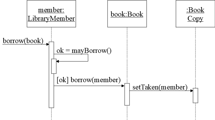
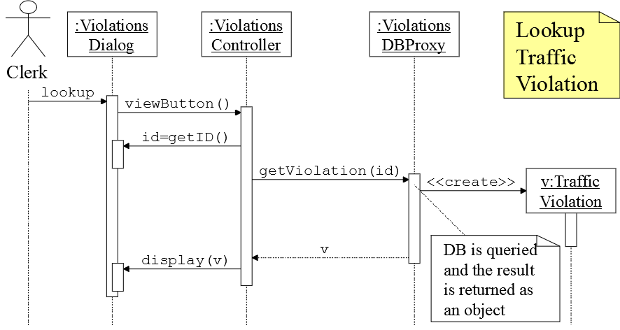
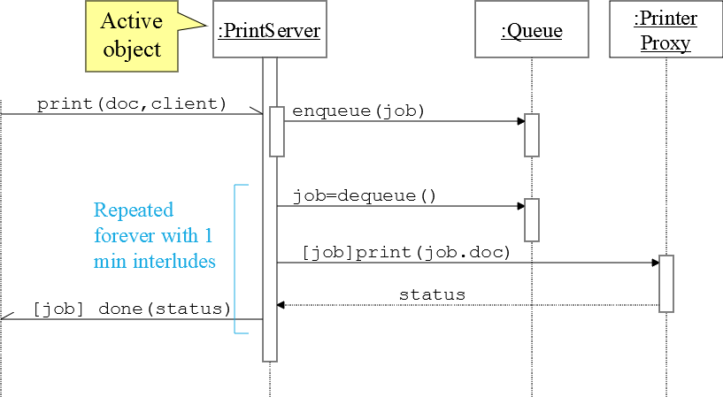
Sequence diagram describes a set of interactions sequences. If we look into class diagram object. Data flow diagram DFD adalah ilustrasi alur sebuah sistem.
UML 1x component diagram. UML 2x component diagram. To draw a guard on a sequence diagram in UML 1x you placed the guard element above the message line being guarded and in front of the message name.
This title overrides the previously specified title if any. Diagram ini dipopulerkan oleh Ed Yourdon dan Larry Constantine pada akhir 1970-an dalam bukunya yang bertajuk Structured Design. Biasanya DFD banyak digunakan oleh seseorang yang bekerja di bidang sistem informasi.
Free Download Free. Learn about UML BPMN ArchiMate Flowchart Mind Map ERD DFD SWOT PEST Value Chain and more. The notation has evolved from the work of Grady Booch James Rumbaugh Ivar Jacobson and the Rational Software Corporation to be used for object-oriented design but it has since been extended to cover a wider variety of software engineering projects.
The word graph is sometimes used as a synonym. Specific operations based on the data can be represented by a. Focuses on the business requirements and many more.
A diagram is a symbolic representation of information using visualization techniques. Focuses more on the blueprint. When it comes to system construction a class diagram is the most widely used diagram.
UML Use Case Diagram. You can put a title for the new page just after the newpage keyword. Overall this is a convenient presentation.
Works on Mac OS X 102 or later Process Flow Diagram Symbols Process flow diagrams use special shapes to represent different types of equipments valves instruments and piping flow. UML guides the creation of multiple types of diagrams such as interaction structure and behaviour diagrams. An activity diagram visually presents a series of actions or flow of control in a system similar to a flowchart or a data flow diagram.
An activity diagram portrays the control flow from a start. It depicts the behavior of a system. Opt fragment in diagram means that the diagram describes two possible interactions sequences - one with the interaction in the opt fragment and another without this interaction.
UML is not a programming language but tools can be used to generate code in various languages using UML diagrams. UML has a direct relation with object oriented analysis and design. Learn from diagram examples and start creating your diagrams online.
The Process Flow Diagram is a graphical representation used to demonstrate major components of a process in an Industrial plant or manufacturer it is widely used in Chemicalpetroleum or process engineering. After some standardization UML has become an OMG standard. Activities modeled can be sequential and.
UML stands for Unified Modelling Language. An activity diagram is a behavioral diagram ie. To understand UML Activity Diagrams we first need to understand what the UML Diagram means.
Such a diagram would illustrate the object-oriented view of a system. Unified Modelling Language UML is a modeling language in the field of software engineering which aims to set standard ways to visualize the design of a system. This is very handy with Word to print long diagram on several pages.
Each link is supposed to take me to the brief explanation and example but numbers 7 10 and 14 dont work. Customer Journey Mapping 18 See All Basic Customer Journey Map Template. Focuses on the actions from a user perspective.
Sometimes the technique uses a three-dimensional visualization which is then projected onto a two-dimensional surface. The newpage keyword is used to split a diagram into several images. Near the very beginning of your UML diagram types page you provide a numbered list of diagram types.
Guards are used throughout UML diagrams to control flow. Diagrams have been used since prehistoric times on walls of caves but became more prevalent during the Enlightenment. In other words UML Diagrams are diagrams that depict how.
The lines between components are often referred to as connectors the implication being that some sort. We describe or depict what causes a particular event using an activity diagram. UML Diagram What is a UML Diagram.
UML is a way of visualizing a software program using a collection of diagrams. It is a standardized set or a collection of diagrams that helps the software developers and software architects to understand the flow of the software. Flowchart Maker and Online Diagram Software.
Diagrams such as Figure 1 are often referred to as wiring diagrams because they show how the various software components are wired together to build your overall application. A sequence diagram is the most commonly used interaction diagram. A data-flow diagram is a way of representing a flow of data through a process or a system usually an information systemThe DFD also provides information about the outputs and inputs of each entity and the process itself.
The Process flow diagrams are used to understand the process and its sequence model a process document a process ensure quality control.
Uml Sequence Diagram Sequence Diagram Helps Us To Understand By Joshua U Medium
Uml Sequence Diagram Sequence Diagram Helps Us To Understand By Joshua U Medium

Free Editable Transaction Uml Sequence Diagram Edrawmax Sequence Diagram Diagram Time Diagram

Uml Sequence Diagram Sequence Diagram Diagram Flow Chart

Free Editable Online Shopping Uml Sequence Diagram Edrawmax Sequence Diagram Time Diagram Class Diagram

Activity Diagram Sequence Diagram Diagram

Uml Tutorial Activity Diagram Example Activity Diagram Flow Chart Template Process Flow Diagram

Uml Sequence Diagram Sequence Diagram Diagram Business Rules

Sequence Diagram Wikiwand

Uml Activity Diagrams Activity Diagram Diagram State Diagram

Sequence Diagram Tutorial Complete Guide With Examples Sequence Diagram Diagram Open Browser

Uml Tutorial Activity Diagram Example Order Processing Business Process Management Business Process Activity Diagram

Login Uml Sequence Sequence Diagram Diagram Ford Granada

4 Phases Of The Project Management Lifecycle Contract Management Change Management Project Management
I Will Design Uml Diagrams Process Mapping And Mockups Through Flowcharts In 2022 Process Map Software Engineer Flow Chart

Uml Sequence Diagram Sequence Diagram Helps Us To Understand By Joshua U Medium

Website Uml Sequence Sequence Diagram Diagram Sequencing